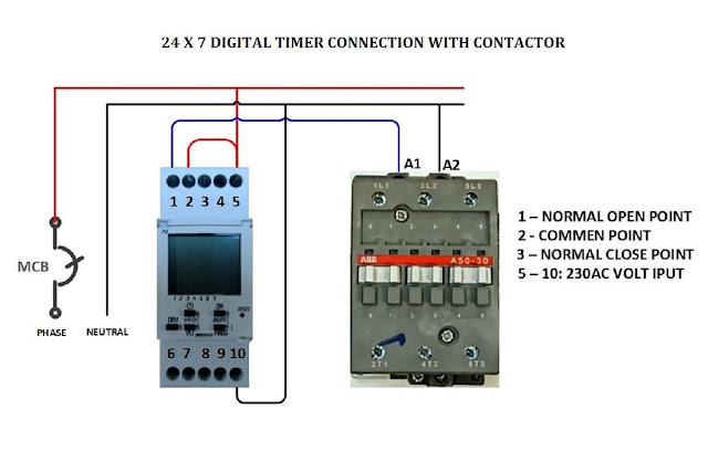
Digital Timer Connection Diagram
How to install 3-phase timer: Timer electrical working principle wiring connection Lighting contactor wiring diagram with timer
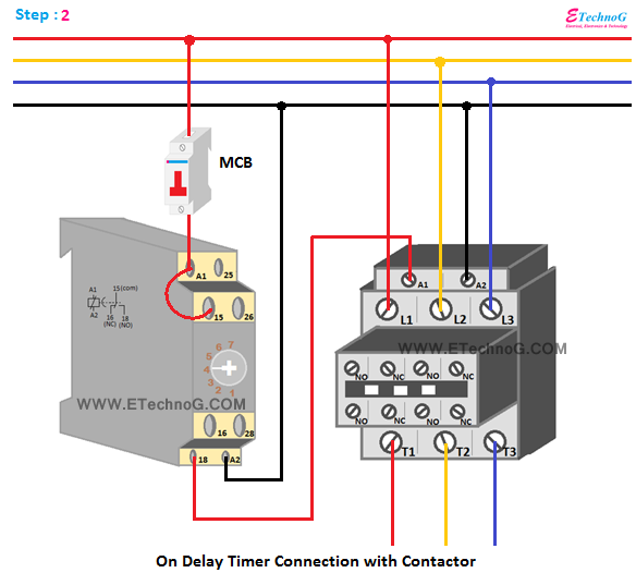
On Delay Timer Connection with Contactor - ETechnoG
Timer diagram wiring anly connection What is electrical timer, working principle of electrical timer, wiring Relay diagram wiring delay timer off layout state solid time base socket connection electrical relays control pins fig electricalacademia motor
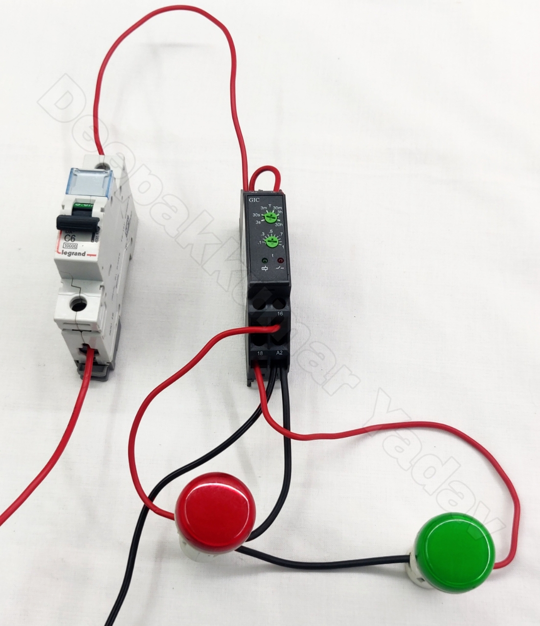
Timer connection diagram
Timer 555 diagram circuit schematic ne555 pinout datasheet block does circuits flip flop works discrete kit eleccircuit integrated output connectionTimer contactor delay phase Wiring switch diagram timer way honeywell need help digital light leviton decora temp trol damper zone switches stack relayOn delay timer connection with contactor.
Switch time analog install photocell contactDigital timer control switch connection and working How to install an analog time switch: a simple guide for beginnersTimer diagram contactor wiring start phase stop pdf circuit momentary install holding volt switches t80 din rail pole parking lot.

Control timer switch connection contactor diagram digital light magnetic panel connect load than
Solid state timerNeed help wiring a 3-way honeywell digital timer switch Single phase motor timer connectionTimer motor phase single connection.
Timer woods wiring issue pro pool wire electricalHow does ne555 timer circuit work .


On Delay Timer Connection with Contactor - ETechnoG

Timer Connection Diagram - YouTube

How does NE555 timer circuit work | Datasheet | Pinout | ElecCircuit.com

How to Install an Analog Time Switch: A Simple Guide for Beginners

Solid State Timer | Solid State Relay Timer | Electrical Academia

electrical - Woods 59104R pro timer issue - Home Improvement Stack Exchange

Lighting Contactor Wiring Diagram With Timer - Wiring Diagram and

What is Electrical Timer, Working principle of Electrical Timer, Wiring

Digital Timer Control Switch Connection and Working

How to install 3-phase timer: